Machining Back Counterbores: The 3 Primary Methods and How to Choose the Right System for Your Application
Back counterboring is a machining process used to create a counterbore on the far side of a hole when direct access is not possible or you want to eliminate the need to flip a part and refixture, in order to reach it with conventional plunge tooling. It is commonly found in all major industries and is often required when a workpiece is being bolted to another component in a final assembly and needs a flat qualified surface for a bolt head, cap screw or washer to seat. It is also common to find back spotfaces in gear housings or other components where a gear or another component needs to slide against it.
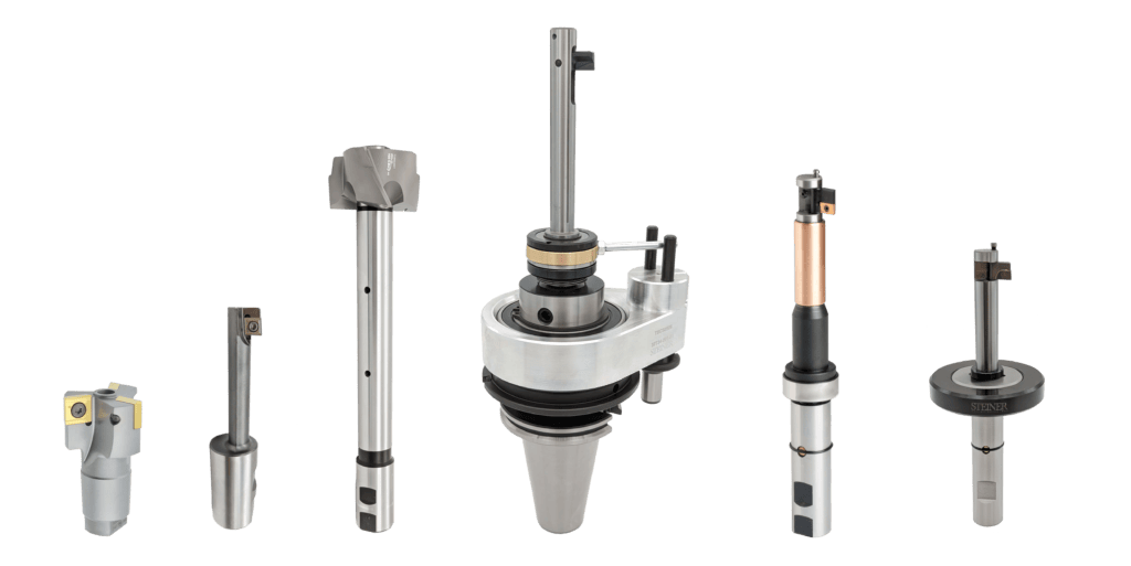
There are three primary methods used to perform a back counterbore:
- Autofacer – Automatic flip open back counterboring tool
- Offset back counterboring tools (often referred to as “flag-style” or “back-boring bars”
- Manual 2-piece back counterboring tools
Each method has specific advantages depending on part geometry, thru-hole/back counterbore ratio, access limitations, tolerance requirements, and production volume.
This guide explains how each system works and which applications they are best suited for.
The 3 Primary Back Counterbore Methods
1. Autofacer – Automatic Flip Open
How It Works
The Autofacer is an automatic back counterboring tool that utilizes a mechanical clutch to physically open or close the cutting blade on the backside of a workpiece. The blade opens either radially from the tool or axially if the thru-hole/counterbore diameter ratio requires it. Typically the thru-hole/counterbore diameter ratio comes in at 2.3xd but can reach upwards of 3xd if application allows for it.
Key Characteristics
- Multiple mechanical clutch systems available
- Tools utilize workpiece thru-hole as a guide when cutting to mitigate tool deflection and allow long reach to diameter ratios
- Different clutches allow for either high or low RPM spindle direction change for opening/closing
- Can use thru-spindle coolant to mechanically open or close
Best Applications
- Medium to high production environments
- Consistent thru-hole diameters
- Applications requiring high degree of reliability
- Long reach through workpieces (due to piloting of the tool)
- Large diameters and reaches (Upwards of 10.500” spotface and reaches of upwards of 4 feet or longer)
Advantages
- High repeatability
- Fast cycle times
- Minimal machine programming complexity
- Good concentricity and perpendicularity with piloted designs
- SAFETY- No operator intervention necessary
- With many clutch systems available, there are no special requirements of the machine-tool the Autofacer is running on
Limitations
- Typically purpose built for a specific application and not intended for “general-purpose”
- Requires a consistent hole making process for the tool to properly pilot
- Typically a custom built tool, though there are stock options and semi-standards available for a lot of applications.
2. Offset Back Counterboring Tools
How It Works
Usually made from solid carbide or heat-treated tool steel, this tool uses an indexable insert.
Offset back counterboring tools are oriented in the tool holder using either Weldon flats or an “orientation flat” ground perpendicular to the cutting edge. Proper orientation is critical for accurate programming and operation.
To run the tool correctly:
- Position the machine spindle centerline over the centerline of the bore you are reaching through.
- Orient the spindle so you know the exact location of the cutting edge.
- Offset the tool in the opposite direction to provide clearance for passing through the hole.
- Once the tool has cleared the hole, move the spindle back to the bore’s centerline.
- Turn on the spindle and pull straight back to reach the desired spotface or counterbore depth.
These tools are designed to cut a single diameter and are not intended for interpolation.
Key Characteristics
- Elliptical shaped neck and cutting edge positioning makes it so piloting is not necessary
- Multiple insert grades, coatings and geometries available to help further reduce
- Tool is suitable for machining only one diameter
- Often used on CNC mills but can be ran on lathes as well
Best Applications
- Low, medium or high volume
- Relatively short lengths of cut
- Relatively short reaches through the workpiece
- Used commonly for standard socket head cap screw and flat head cap screw sizes
Advantages
- Solid tools mean no moving parts, so inherently very reliable as long as tool deflection can be mitigated.
- Cost-effective
Limitations
- Since these tools are not piloting, you are more limited with length-to-diameter ratios
- Since tool is not piloting, you usually will run lighter speeds and feeds = slightly longer cycle times
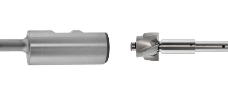
3. Manual Back Counterboring Tools (2-Piece Systems)
How It Works
A straight shank or Morse Taper holder will feed down through the hole in your workpiece and then a programed stop will stop the spindle. At this point the machine operator will reach into the machine tool and manually affix a 4-flute HSS or brazed carbide cutter on the end of the arbor via a bayonet locking system. The operator will then proceed to machine the back counterbore and then manually take off the cutting head prior to the arbor coming out of the hole in the workpiece and moving to the next hole location to repeat the process.
Key Characteristics
- HSS or brazed carbide 4 flute cutting eads
- Straight shank or Morse Taper shanks
- Fully manual system
Best Applications
- Prototype environments
- Low quantity production
- Running workpieces on radial arm drill presses or similar manual machines
Advantages
- Very cost effective
- Standard sizes readily available for quick turn-around
- Ideal for short runs and R&D
Limitations
- Longer cycle times
- Less efficient in high-volume production
- Safety is a large concern for these types of tools, especially when running on larger machines which may require the machine operator to walk out onto the machine table or climb a fixture to manually attach the cutter head.
Final Thoughts
Back counterboring is not a one-size-fits-all process. The optimal system depends on part geometry, material, tolerance demands, and production volume.
Mechanical flip-open systems and offset back boring bars dominate high-volume manufacturing. Manual back counterbore tools are typically seen in lower production job-shop type environments where cycle time isn’t as big of a concern.
Selecting the right method ensures your ability to make the most of every second your machine spindles are or are not running.